Most trusted Cetop square flange manufacturer in India
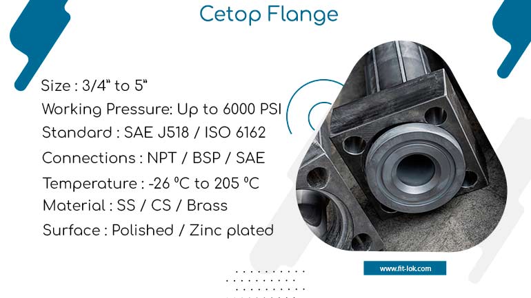
CETOP flanges are compatible and therefore interchangeable with other CETOP as well as ISO standard fittings used in the hydraulic applications. These standardizations also helpful in the maintenance and various kinds of repair work; likewise they are useful when there are upgrades required on the systems. CETOP Square flanges are usually furnished with O-ring groove or gasket groove that ensures a close fit. This feature avoids leakage of hydraulic fluid that is very important in high pressure systems for efficiency and safety. We are one of the reliable CETOP flanges manufacturer in India and can supply in wide range of sizes.
Stainless steel cetop flange are constructed for high-pressure applications; most of them are made for operating between 6,000 psi and more based on material and size. They also come with a temperature variance functionality to make them operate well in any condition of the climate. Flange cetop 250 have been designed for ease of connection and disconnection, which means that systems are easier and cheaper to maintain. They have the standard bolt holes through which they can easily be fixed and secured to other parts of the hydraulic system.
Flange cetop 250 are designed as per ISO 6164
The face of the flange is generally accurately turned to provide a good fit between the flange gasket nut and the mating part. This minimizes the probability of fluid leakage and increases performance of the seal. Due to these factors, CETOP flanges are normally galvanized where the flange will be likely to be exposed to adverse conditions such as marine or offshore environments.
The most standard sizes are according to the port or pipe diameter which can be classified as small diameter and big diameter in accordance to the system demand. The sizes normally range from 1/4 inch to several inches such as 6 inches or even more where they depend with the hydraulic flow of a certain system. Cetop square flange thickness can be different due to the pressure and material characteristics. For the high pressure situation or system, thick flange is preferably used, but thin flange may work in the low pressure situation.
Table of content
| Type | Cetop flange |
| DESIGN | SAE J518 C / ISO 6162 / ISO 6164 / JIS B2291 |
| MATERIAL | CS, SS 304, SS 316, SS 316 TI, ALLOY STEEL, DUPLEX, SUPER DUPLEX, INCONEL, MONEL, HASTELLOY, SMO 254, 904 L, TITANIUM |
| WORKING PRESSURE | UPTO 210 BAR (3000 PSI) & 420 BAR (6000 PSI) & 700 BAR (10,000 PSI) CUSTOMISED |
| CODE | CODE 61 FLANGE (3000 PSI) & CODE 62 FLANGE (6000 PSI) |
| SIZE RANGE | 3/8″ (DN 10) TO 5″ (DN 125) |
| CONNECTIONS | BUTT WELD, SOCKET WELD, THREADED (BSPP, NPT, METRIC, JIC) |
| BODY TYPE | FORGED, BAR STOCK |
| FLANGE ACCESSORIES | O-RING, BOLT, NUT, WASHER |
| O-RING MATERAL | NITRILE, BUNA 90 SHORE, VITON 85-90 SHORE |
| BOLTS MATERIAL | HIGH TENSILE 8.8 GR, 10.9 GR, 12.9 GR, SS 304, SS316 |
| SURFACE | CARBON STEEL – BLACK PHOSPHATED, TRIVALENT ZINC PLATED, |
| STAINLESS STEEL – ELECTROPLATING, NATURAL FINISH |
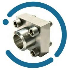
Cetop flange
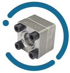
Cetop square flange
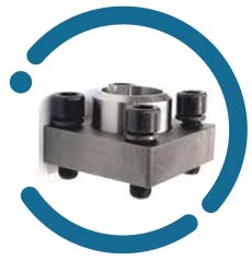
Flange cetop 250
| Working Pressure Kg/cm2 | Size | A | B | C | D | E | F | G | H | L | Screws (Metric) | Screws (UNC) | Or Type | Weight (Kg) |
|---|---|---|---|---|---|---|---|---|---|---|---|---|---|---|
| 414 | 1/2″ | 21,5 | 15.8 | 40,49 | 57 | 18,24 | 46 | 36 | 16 | 9 | M8x30 | 5/16×1″1/4 | 4075 | 0,24 |
| 414 | 1/2″ (3/8″) | 17,5 | 15.8 | 40,49 | 57 | 18,24 | 46 | 36 | 16 | 9 | M8x30 | 5/16×1″1/4 | 4075 | 0,22 |
| 414 | 3/4″ | 28,0 | 20.9 | 50,80 | 71 | 23,80 | 55 | 35 | 21 | 11 | M10x40 | 3/8×1″1/2 | 4100 | 0,48 |
| 414 | 1″ | 34,0 | 26.6 | 57,15 | 79 | 27,76 | 68 | 41 | 21 | 13 | M12x45 | 7/16×1″3/4 | 4131 | 0,64 |
| 378 | 1″1/4 | 42,8 | 35.1 | 66,68 | 93 | 31,75 | 78 | 44 | 25 | 15 * | M14x45 | 1/2×1″3/4 | 4150 | 1,00 |
| 320 | 1″1/2 | 48,6 | 40.9 | 79,38 | 112 | 36,50 | 94 | 55 | 30 | 17 | M16x50 | 5/8×2″ | 4187 | 1,68 |
| 250 | 2″ | 61,0 | 52.5 | 96,82 | 134 | 44,45 | 114 | 65 | 37 | 21 | M20x70 | 3/4×2″1/2 | 4225 | 2,86 |
| 230 | 2″1/2 | 76,6 | 62 | 123,80 | 180 | 58,70 | 152 | 80 | 45 | 26 | M24x80 | – | 4275 | 6,40 |
| 200 | 3″ | 90,0 | 77.9 | 152,40 | 208 | 71,40 | 178 | 90 | 55 | 33 | M30x100 | – | 4337 | – |
| Metric Size | Flange Size | Screw Thread | Screw Torque (NM) |
| 13 | 1/2″ | M8 | 32 |
| 19 | 3/4″ | M10 | 70 |
| 25 | 1″ | M10 | 70 |
| 32 | 1 1/4″ | M10 | 70 |
| 38 | 1 1/2″ | M12 | 130 |
| 51 | 2″ | M12 | 130 |
| 64 | 2 1/2″ | M12 | 130 |
| 76 | 3″ | M16 | 295 |
| 89 | 3 1/2″ | M16 | 295 |
| 102 | 4″ | M16 | 295 |
| 127 | 5″ | M16 | 295 |
- Easy Installation
- Interchangeability
- Sealing Options
- Temperature Resistance
- Corrosion Resistance
- Injection Moulding Machinery
- Aluminium Die-Casting Machinery
- Sintering Machinery
- Industrial Hydraulics
- Steel Mills
- Hydraulic Presses
